
I think that every aeromodeller has a dream of building one particular model; some see their dreams come true, others just carry on dreaming. In my case my dream lasted for approximately fifty years.
It was when stationed at Leuchars -circa 1956- that my aeromodelling really took off. The officer in charge of the club built a free flight twin engine Wayfarer. I cant remember what the engines were, but they were controlled by a pendulum. Some of you old soaks will remember the system. This model impressed me very much and twins have lurked in the back of my mind ever since.
The Twin Pin came into being in 1957 and I remember reading about it at the time and was impressed with its performance. We now fast forward to 1979. I was getting a magazine at the time called Wings and in part 102 was an article on the Twin Pin. This article convinced me that this was the twin I wanted to build. I immediately sent off to Scottish Aviation to see if I could get some plans. I received an A4 sheet on which was an outline plan. SA explained that this was the only plans that they had and that it was a micro film copy. I then spent a long time getting more information and I ended up with quite a reasonable sized file.
Fast forward to 2006 and having by this time built quite a lot of electric models, I suddenly remembered the Twin Pin. I started drawing plans for a 76.5 model which was 1:12 scale and one night my good friend JJ came to see me with a copy of an old RCME, in which was a photo of a Twin Pin built by Mike Trew.
I contacted Mike and bought a set of outline plans and a set of engine nacelles. The plans were for a model of 110! When trying to decide whether to go ahead I quickly realised that things like scale Fowler type flaps would be much easier with the bigger model and the way that the electric scene was progressing, power was not going to be a problem. Hence, with a lot of support from my Pal, the Twin Pin finally was going to be built.
I should say that the plans were only outline plans with no details on Fowler flap mechanism or how to operate the three rudders. Neither were there any real construction details except for wing rib, fin and tail plane sections. The only real construction detail was the fuselage main structure.
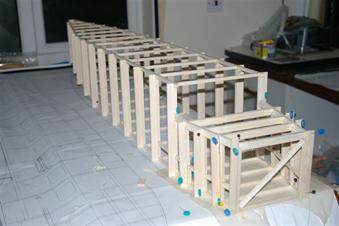
The fuselage main structure (above) is a basic square frame made from ¼ square balsa the shape of the fuselage came from formers glued to the main frame and then the whole fuselage was planked with 3/32 balsa strips. Mike Trew used 1/8 balsa for the planking, but I was concerned about the weight especially when thinking about batteries. I decided to use the scale hatch at the front, which will house the receiver and the Rx battery. The hatch will also allow access to the rudder and elevator servos.
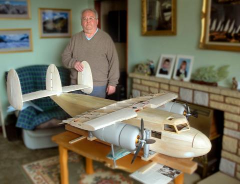
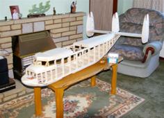 The fuselage is enormous, but I wanted to try and get the batteries as far as possible up front, so I have made the cockpit removable, which gives more than adequate access. I can actually
lose my arm inside the fuselage through the cockpit hatch.
The fuselage is enormous, but I wanted to try and get the batteries as far as possible up front, so I have made the cockpit removable, which gives more than adequate access. I can actually
lose my arm inside the fuselage through the cockpit hatch.
The fins and rudders were quite a challenge as there were no details on how the outer fins were attached to the tail plane and no details on how to operate the three rudders. I therefore spent some time experimenting with different methods for rudder operation, because I wanted to keep the controls completely hidden as in the full size. Finally this was achieved. The next wee problem was the scale hinging; sixteen in all. Each hinge was made from three pieces of ¼ light plywood with a pin through the middle. This took some time to complete and later I almost regretted all the work when I realised that the hinges were almost completely hidden. Having said that it was a labour of love and thats how it should be when you decide on a project of this scale. My workshop is not very big and by this time with the completion of the fuselage and tail plane it was beginning to fill up. I therefore decided to build the aircraft in sub assemblies and carry out a final assembly when the wings, undercarriage etc were complete.
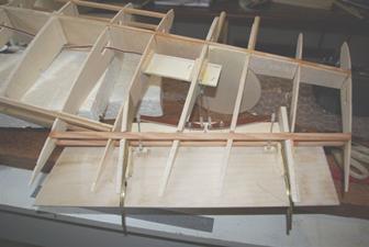
The next assembly was the undercarriage. Mike used solid balsa r einforced with carbon fibre for the undercarriage support. I thought about that and being worried about weight, decided to build the assembly like a wing with a main spar and ribs skinned with 3/32 balsa. The main spar was made with a sandwich of 1/16 ply on the outside and hard balsa in the middle with lightening holes. The u/c legs are made of thick walled aluminium tubing with a steel rod a sliding fit in the tube. Springs are used on top of the rods and two slots are cut in the tubing and a pin goes though the slot and is a tight fit in the steel rod. This keeps the two wheel assembly in the correct position ie facing forward. Each leg assembly is then mounted onto blocks up in the main spar. I have to manufacture the springs myself as I cannot get anything to fit commercially.
The wing centre section was next assembly. Again I made the main spar from a sandwich of 1/16 ply and ¼ hard balsa. This may sound a bit on the hefty side, but this spar has to carry the two motors (AXI 4120/14 gold line) and transfer the power (about 500 watts per motor) to lift a model of around eleven pounds. I made light ply formers for the engine nacelles. This again had to be my own design as the original plans were for two 52 i/c engines. Two of the formers carry the motors. It was about this point that I read an article in one of magazines about scale plastic engines. The sizes being written about seemed just right for the Twin Pin. I sent off for one engine to see if it would be suitable and on receipt of the engine it was found to be a perfect size for the engine nacelles. It was also about this time that I realised how complicated the centre section was going to be. Motors and motor wires, two servos with the Fowler flap mechanism, extension cables, wing joiners for the outer wing panels and u/c mountings. I decided that I had better make a checklist otherwise the whisky soaked brain would forget something and complete the sheeting.
The flaps are quite large -16x3½ approx - and getting material 3/32 thick that would not flex much proved a problem. This was solved by making a sandwich of 3 x 1/32 balsa- cross grained -and tissue in between and glued with a very thin smear of epoxy resin. The Fowler flap mechanism took a lot of experimentation. The first problem was that the normal servos did not give anywhere near the amount of movement required to operate the flaps fully, so the first thing was to calculate the required movement. Not being very bright I had to make a mock up using the true sizes of the flaps and how far they had to travel. It worked out that I would need amplifying arms of a ratio of 3:1. That means that the servo travel was increased by a factor of 3 which gave a movement of about three inches, the amount required.
 The next problem, what was going to guide the flaps backwards and downwards? I decided to use U shaped brass. I then made a jig of the correct curve for the brass guides and heated the
brass and bent it into shape. I required eight pieces in all, there being two flaps in each wing. The flaps would have two mountings with two steel spigots which would travel along the brass guides, but how could I get the flaps to travel smoothly
down the guides without creeping and jamming. I think the answer is shown in the bottom picture which shows the final assembly. The picture (below right) shows the flaps fully extended. I think that these flaps are not so much to slow the aircraft
down the aircraft was slow enough but act as lift enhancers to give a very good short take off and landing.
The next problem, what was going to guide the flaps backwards and downwards? I decided to use U shaped brass. I then made a jig of the correct curve for the brass guides and heated the
brass and bent it into shape. I required eight pieces in all, there being two flaps in each wing. The flaps would have two mountings with two steel spigots which would travel along the brass guides, but how could I get the flaps to travel smoothly
down the guides without creeping and jamming. I think the answer is shown in the bottom picture which shows the final assembly. The picture (below right) shows the flaps fully extended. I think that these flaps are not so much to slow the aircraft
down the aircraft was slow enough but act as lift enhancers to give a very good short take off and landing. 
The one other thing I noticed also at this stage and that was, even at this size of model the wing section was such that the wing leading edge operational slats were going to be very difficult. I think that is why Mike Trew did not fit them. I thought long and hard about this but finally concluded not to fit them. I think the final decision was made after reading an article about LE slats, where the author said that if you did not get the correct gaps between top and bottom when the slats were open, it made the model very unstable. I must admit that I am a wee bit disappointed but as I could not guarantee myself that I could build and set up these flaps correctly, that there was no point in taking the chance of making an unstable model. That said it would look nice to see them in operation while the model was static, Watch this space!
I was given a prop size suitable for the motors from John Emms at Puffin and again I read an article on variable pitch props. I contacted the supplier and ended up buying two units. These props are not variable pitch in the true sense; that is, they do not alter pitch during flight, but it does allow you to carry out tests for maximum efficiency. When the props are assembled you can slacken the main central nut and there is a screw in the hub which can be turned by a small screwdriver. Turning the screw alters the pitch of all three blades by the same amount. On the tests I have done so far it seems to work very well. To give you some idea the difference in 1 in pitch makes a huge difference to the power output! It made me realise that we should definitely experiment more when fitting our props to our motors if we want optimum performance. I will make a table of results when I finish my testing.
The three bladed props look very scale like and really look good on the model.
The tail plane is now fitted and the rudders and elevators are working as they should. With the centre section fitted my workshop is getting very congested with very little room to build the outer wings.
The fuselage fitted with tail plane and wing centre section has taken up residence in the living room. Its a good job I do not have a her indoors.
I had hoped to be further on with the Twin Pin, but things like long holidays and various commitments got in the way.
I was not happy with the way I had joined the centre section onto the fuselage, as most of the load (hopefully no more than 5 kilos) was being taken by the top fuselage longerons which were only ¼ square hard balsa. Some of the load was also being taken by the u/c sponsons, but I decided to spread the load over more of the airframe.
This modification was carried out by making four light ply brackets which fitted inside the fuselage and tied the centre section into the fuselage. These brackets allowed the load to be spread over a larger area of the fuselage including the bottom longerons and the uprights.
I also spent quite a bit of time testing the motors. This proved to a very useful exercise. I would advise those who do not have a watt meter to buy one. (The price of these meters has dropped quite a lot since I bought mine).
By reading the motor data, it was established that the maximum amps for the motors was 46 amps. If you remember from my last article I decided to use variable pitch three bladed props of 12 diameter. The voltage to be used is 14.8V
The recommended prop size was 12 x 8. So I started my testing with props set at this pitch. The following were the test results.
PITCH AMPS WATTS
12x8 38 389
12x9 42 432
12x10 46 (max) 498
I have simplified the test table, as I tried a lot more pitch sizes.
This is where the use of a watt meter proved very useful, because if you simply multiply the volts by the amps you only get a theoretical wattage and not a working wattage. The other point I would make is that the meter allows you to get the maximum power out of the motor. I recently convinced my friend to buy a meter as he was having quite a bit of trouble with his ESCs. When he checked with my meter he found that he was over propping his models and hence using too many amps for the ESCs and the motors.
I also experimented by making a wiring harness which allowed both motors to see both batteries. I tried this because I read an article about two identical batteries producing different amounts of power which could be nasty on a twin.
However, I checked with John Emms of Puffin models and he said not to worry just give one motor one battery and all will be well. Heres hoping!
Well after all that, I have around a kilowatt of power, which should give me about 80 watts a pound. Since I am not looking for supersonic speeds, I hope this will be enough.
The other item that I spent quite a time on (too much time) was springs for the u/c telescopic legs. I was determined to make them myself. I tried various piano wire gauges, but soon realised that the thickness of the wire required was going to require Desperate Dan style arms to pull the wire round a suitable bolt.
However going back to my training days when we used to heat treat steel using different methods to obtain different results such as, annealing, hardening, tempering and toughening, I decided to anneal the wire so that I could bend it round the bolt and then harden and temper it after.
They say a bad tradesman always blames his tools, but it soon became obvious that trying to reach the correct temperatures for these processes using a blow torch was impossible. Well thats my excuse!
Frustation took hold and I got up one morning and went onto the internet, placed an order within a few minutes and received the springs the following morning.
Enough said!
I decided to cover the woodwork in the good old tradition using tissue and dope. I had forgotten the finish that can be achieved when you mix Johnsons baby powder and dope. As you can imagine, because of the size of the model, it meant that I was working with dope for fairly long sessions and that was the other thing I had forgotten i.e. the fumes. The benefit is that my whisky bill has dropped lately.
The outer wing panels are almost complete. The aileron servos are fitted and I have managed to operate the ailerons with hidden controls as per the full size. I am in the process of making the wing retainers and stays. I am also installing nav lights.
The plumbing (i.e. wiring) is installed but I think I will use interference chokes at the receiver end, because the motor wires are quite long and although I have tried to keep them well apart from the control wires, I think I will play it safe.
All being well finishing should be around Feb March next year, unless holidays get in the way. Hope to have some photos next time.
My long running project of the Scottish Twin Pioneer is slowly nearing completion. However, it's the little bits that take the longest and Ive been working on perfecting the control surfaces, particularly the flaps to get them spot on.
The pictures show you the detail.
The ailerons are of the Freise type, and I have managed to hide the control rods as can be seen. Once the final adjustments have been made a scale panel will be fitted over the ball joint (see right).
 |
 |
|
The flap mechanism at closed. Two flaps per wing. |
The flaps in the open position. |
 |
 |
| A side view of a wing showing both flaps deployed. | Here she goes all complete and now ready for her “claes”. |
Thats all folks, hopefully the final chapter next year will be the flying bit.
Cheers the noo.
When I started this project, I wanted something to keep me building for some time, because the house was rapidly filling up with models. Well the Twin Pin has certainly fulfilled its purpose as it has been six years in the making and still not quite complete.
I was hoping to have carried out taxi trials by now, as I am a bit worried by the weight. However the weather has been terrible lately and when a suitable day did appear, my test pilot was not available. So I have given up on that idea mainly because when checking the physical size of more powerful motors it will only push the props forward by about 2 mm and that I will be able to use the existing motor mounts.
The model is now fully sheeted and almost ready for spraying, but this will have to be carried out when the weather warms up as I do not have a spray booth in the back yard. As can be seen in the photos I have started applying some detail. I found in the Squires catalogue some half round polystyrene strips which was easily cut and applied with balsa cement. Having said that the application of the strips is quite time consuming e.g each aileron has forty strips!
By the way I decided to give the flaps their own set of batteries, because there are four servos which take quite a bit of power.
I will let the photos tell the rest of the story.
Cheers the noo, Sandy
click on left or right of picture to move through slides
click off picture to return to this page