
 Balsa Basics
 by Mike Pirie
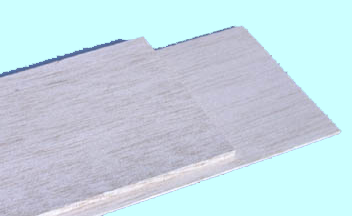
Balsa selection has always been important for us glider guiders, but now with the increasing popularity of electric models, it has become even more important to choose wood which will result in the lightweight airframes required. The main considerations when selecting wood, are grain direction, stiffness and weight. The first two are fairly self evident, but the third, the weight, is not always so obvious, and the only sure way of establishing its weight, or density, is to weigh it accurately.
With this purpose in mind, I devised, a few years ago, a table of multiplication factors (shown below) to aid in the calculation of densities for sheets of various sizes. Once the density has been established, I clearly mark the value on to the sheet using a felt tip marker. Balsa densities vary between 6 and 14 lbs/cu ft but heavier and lighter pieces are occasionally encountered. To use the table, simply weigh the balsa sheet in grams, and, using the appropriate multiplication factor from the table, calculate the density. The third column in the table is for an individual square inch and can be used for odd shaped pieces whose area in square inches, is known.
Remember to leave on the weight information on when cutting pieces off the sheet. This way even the small pieces which end up in your scrap box will be marked with the correct weight information shown.
With regards to weighing equipment, digital balances weighing up to 1200g in 1g steps can be obtained from Quicktest, but are rather expensive. A cheaper option would be the postal scales sold by Mike Woodhouse of Free Flight Supplies for £5.75. They weigh up to 100g in 1g steps. Happy building.
| 3x36 | 4x36 | 1x1 | |
| Sheet | D = W x MF | ||
| 1/32 | 1.129 | 0.846 | 121.90 |
| 1/16 | 0.564 | 0.423 | 60.95 |
| 3/32 | 0.376 | 0.282 | 40.63 |
| 1/8 | 0.282 | 0.212 | 30.48 |
| 3/16 | 0.188 | 0.141 | 20.32 |
| 1/4 | 0.141 | 0.106 | 15.24 |
| 3/8 | 0.094 | 0.070 | 10.16 |
| 1/2 | 0.070 | 0.053 | 7.62 |
by George Whelan
Over the past couple of years I have flown a number of ARTF models from Puffin Models, while these are well made models and good flyers I still like to cut and glue sticks.
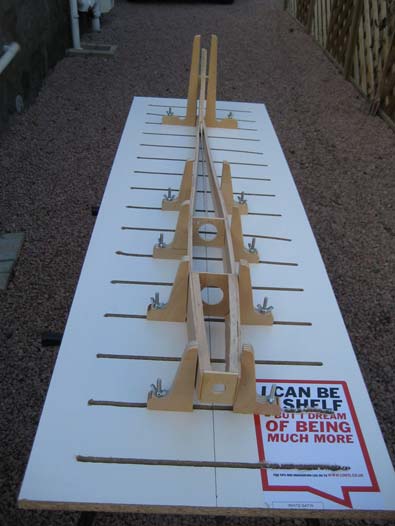
As the Winter draws on I decided to set a production line and build an Elektra 7 electric soarer, a Sagitta 600 with ailerons for the slope and a Sagitta 900 model for next years 100S Nationals. These models are traditional construction being entirely built up from balsa, ply and spruce.
Despite having built many of this sort of model I still am not confident in building straight fuzzes no matter how many clamps are applied. The answer is to clamp the fuz to something i.e. a jig.
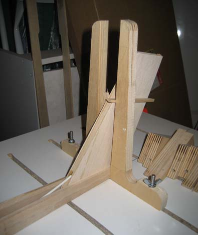
Looking on the Internet at the available options it was down to the SLEC jig or a build it yourself, many people (Norrie) have used the SLEC for years, but I decided to go down the build your own route. I mulled over a number of ideas including adjustable cradles built onto a tube or box section, however I decided to go for the right angle brackets on a board method.
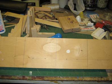
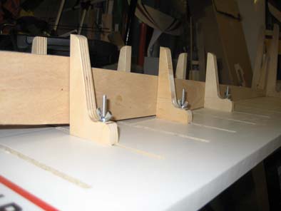
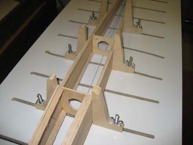
So to the shed, looking around I came across some good 12mm ply from a chest of draws I demolished, ideal for the brackets. I got some graph paper and drew up a couple of shapes before deciding on a final shape based on the size of wood available, this shape was transferred to the wood giving me 5 pairs out of one piece. Using my band saw and Fostner drills I very quickly cut out the brackets and fettled them up on my sanding disk. I was very pleased with the product and decided to cut up another piece, making one pair extra long for fin alignment.
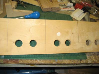
The brackets would be held onto the board with M5 X 60 screws and wing nuts, this meant that any side to side adjustment would need to be incorporated into the board via slots.
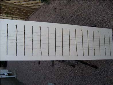
The board is a piece of Conti board with M5 slots routed from side to side at 75mm spacing. This was a learning curve for me, She who must be obeyed bought me an excellent router for Christmas 2 years ago and this was the first time I have tried heavy duty routing, probably about 90% success, from the photo you can see the odd wobble, however the whole thing works a treat, straight fuzzes from now on. I have included some photos, which tell a thousand words. The only addition is a centre line drawn down the board for alignment.
 |
 |
 |
Main lesson learned, use strong clamps for the router guide or it will drag you all around the shed. Wear a mask and goggles as the dust gets everywhere.
by George Whelan
Following my presentation on cutting foam wings I thought it would be a good idea to do an online presentation as an aide memoir for anybody who fancies having a go. I have been cutting wings for years and my method has evolved from very simple to complex and back to the current simplified method.
Why Foam
Materials
ALL THESE FOAMS WHILE NOT TOXIC SHOULD BE CUT IN A WELL VENTILATED SPACE
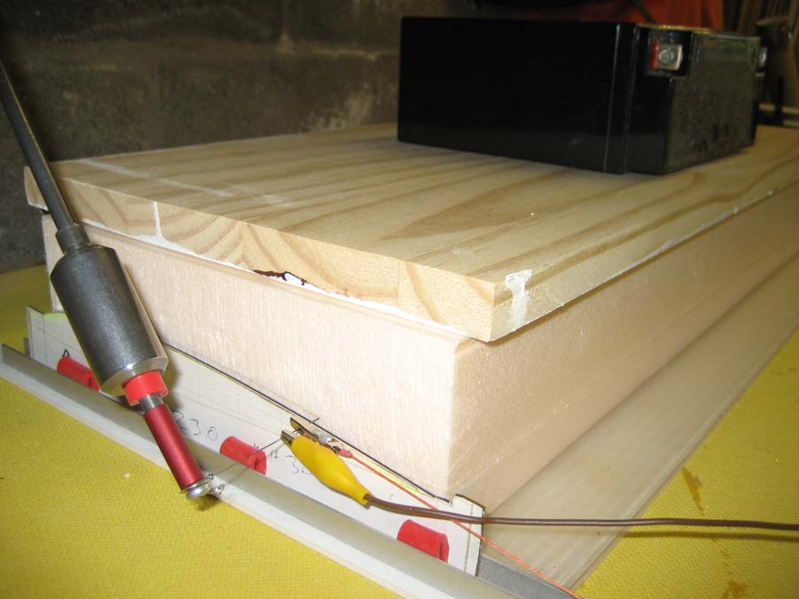
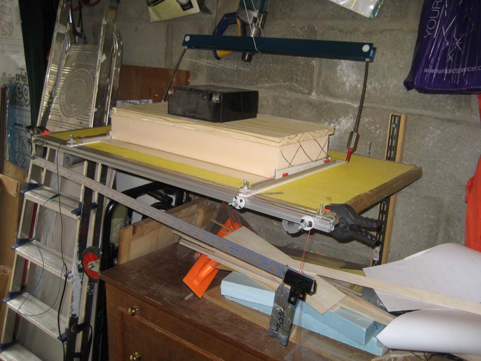
Bows
 I have a variety of bows in different lengths up to about 1 meter long, longer than this the drag on the cutting wire makes the profiles inaccurate. You can still make long wings; you just do it by gluing a number of panels together. I use this method for making multiple taper panels. I used to use a standard car battery charger for powering my bows, this was more than adequate and safe, and they are cheap enough to buy if you don’t already have one. For me using a 240-volt light dimmer switch is scary, take care with anything electric, and remember you will be handling this equipment. Cutting wire is available from the likes of SLEC, you could use a guitar string, and my first source of wire was an electric fire element, just wind the required length of the element. My power supply is a Variac transformer which can be turned up to 275V ac. I have this pegged at a maximum of 24 volts. However I do not use voltage to regulate the cutting speed I use current, hence the dvm. I have one type of wire that cuts well at 2.45 amps and another that cuts well at 4.25 amps. If you use amps to drive the cutting wire then it will be constant regardless of the length of bow.
Templates
Cutting Board
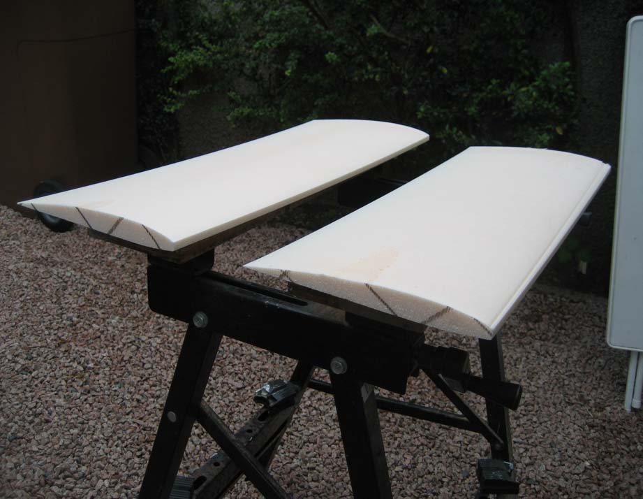
Once you have your wing panels you can glue them together, install a joining mechanism and glass and bag them, but that’s another story.
S.W.G (Inches) |
Wire No Gauge. |
A.W.G or B &S (Inches) |
A.W.G Metric (mm) |
0.500 |
0000000 (7/0) |
||
0.464 |
000000 (6/0) |
0.580000 |
|
0.432 |
00000 (5/0) |
0.516500 |
|
0.400 |
0000 (4/0) |
0.460000 |
11.684 |
0.372 |
000 (3/0) |
0.409642 |
10.404 |
0.348 |
00 (2/0) |
0.364796 |
9.266 |
0.324 |
0 (1/0) |
0.324681 |
8.252 |
0.300 |
1 |
0.289297 |
7.348 |
0.276 |
2 |
0.257627 |
6.543 |
0.252 |
3 |
0.229423 |
5.827 |
0.232 |
4 |
0.2043 |
5.189 |
0.2120 |
5 |
0.1819 |
4.621 |
0.1920 |
6 |
0.1620 |
4.115 |
0.1760 |
7 |
0.1443 |
3.665 |
0.1600 |
8 |
0.1285 |
3.264 |
0.1440 |
9 |
0.1144 |
2.906 |
0.1280 |
10 |
0.1019 |
2.588 |
0.1160 |
11 |
0.0907 |
2.304 |
0.1040 |
12 |
0.0808 |
2.052 |
0.0920 |
13 |
0.0720 |
1.829 |
0.0800 |
14 |
0.0641 |
1.628 |
0.0720 |
15 |
0.0571 |
1.450 |
0.0720 |
16 |
0.0508 |
1.291 |
0.0640 |
17 |
0.0403 |
1.150 |
0.0480 |
18 |
0.0403 |
1.024 |
0.0400 |
19 |
0.0359 |
0.9119 |
0.0360 |
20 |
0.0320 |
0.8128 |
0.0320 |
21 |
0.0285 |
0.7239 |
0.0280 |
22 |
0.0253 |
0.6426 |
0.0240 |
23 |
0.0226 |
0.5740 |
0.0220 |
24 |
0.0201 |
0.5106 |
0.0200 |
25 |
0.0179 |
0.4547 |
0.0180 |
26 |
0.0159 |
0.4038 |
0.0164 |
27 |
0.0142 |
0.3606 |
0.0148 |
28 |
0.0126 |
0.3200 |
0.0136 |
29 |
0.0113 |
0.2870 |
0.0124 |
30 |
0.0100 |
0.2540 |
0.0116 |
31 |
0.0089 |
0.2261 |
0.0116 |
32 |
0.0080 |
0.2032 |
0.0100 |
33 |
0.0071 |
0.1803 |
0.0092 |
34 |
0.0063 |
0.1601 |
0.0084 |
35 |
0.0056 |
0.1422 |
0.0076 |
36 |
0.0050 |
0.1270 |
0.0068 |
37 |
0.0045 |
0.1143 |
0.0060 |
38 |
0.0040 |
0.1016 |
0.0052 |
39 |
0.0035 |
0.0889 |
0.0048 |
40 |
0.0031 |
0.0787 |
0.0044 |
41 |
0.0028 |
0.0711 |
0.0040 |
42 |
0.0025 |
0.0635 |
0.0036 |
43 |
0.0022 |
0.0559 |
0.0032 |
44 |
0.0020 |
0.0508 |
0.0028 |
45 |
0.0018 |
0.0457 |
0.0024 |
46 |
0.0016 |
0.0406 |
0.0020 |
47 |
0.0014 |
0.0350 |
0.0016 |
48 |
0.0012 |
0.0305 |
0.0012 |
49 |
0.0011 |
0.0279 |
0.0010 |
50 |
0.0010 |
0.0254 |