
Mike's Mammoth 8 Engine Wonder
 On the 2nd November, 1947, Howard Hughes flew his ‘Spruce Goose’ on its
first flight above Long Beach Harbour, Los Angeles. It never flew again. It was, and
still is, the largest flying boat ever built, and is now on display at the Evergreen
Aviation and Space Museum in Oregon, US.
On the 2nd November, 1947, Howard Hughes flew his ‘Spruce Goose’ on its
first flight above Long Beach Harbour, Los Angeles. It never flew again. It was, and
still is, the largest flying boat ever built, and is now on display at the Evergreen
Aviation and Space Museum in Oregon, US.
The actual H-4 airborne on its only flight of 26 seconds
Encouraged by the success of my 1/38 scale B-36, I was itching to have another go at a scratch build. I had done six engines, so what next? Well eight engines of course, the Spruce Goose! The model would be of similar size and follow the same construction principles as the B-36, i.e. built up balsa/liteply fuselage, foam veneer wings and the NACA 2415 aerofoil.
 Following a search on the internet, I purchased a detailed blueprint of the Goose from
www.aviationshoppe.com, a US
based company specialising in aviation goodies.
Following a search on the internet, I purchased a detailed blueprint of the Goose from
www.aviationshoppe.com, a US
based company specialising in aviation goodies.
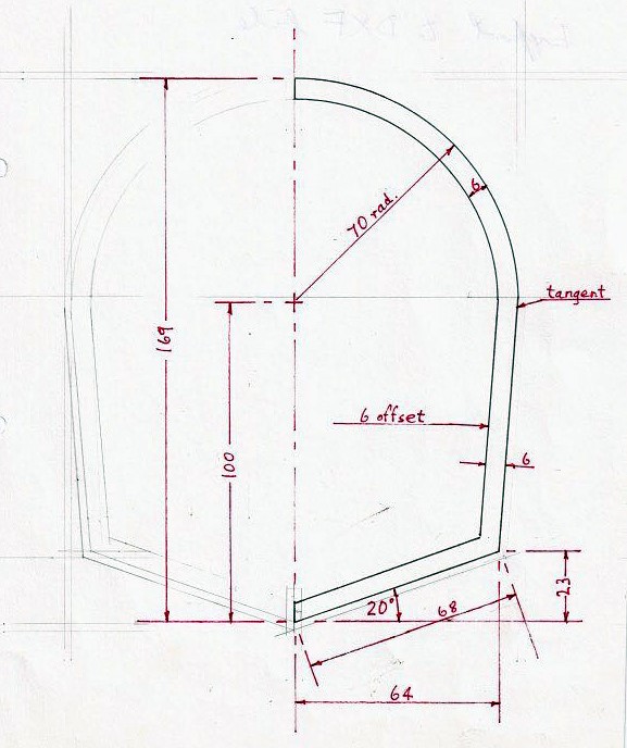
Taking measurements off the blueprint and scaling them up, allowed me to draw side and top elevations from which I could create the cross sections necessary for the laser cutting of the formers. The drawings of the formers were translated into files using Adobe Illustrator Ai, a vector based graphic design package which I downloaded for free on a seven day trial basis. The files were exported as DXF files, stored on an SD card, and taken down to the local laser-cutting shop MAKE Aberdeen (now closed unfortunately). Two sheets of 3mm liteply were used, one for each half of the fuselage. Total machine time was 12½ minutes - slightly faster than a fret-saw!

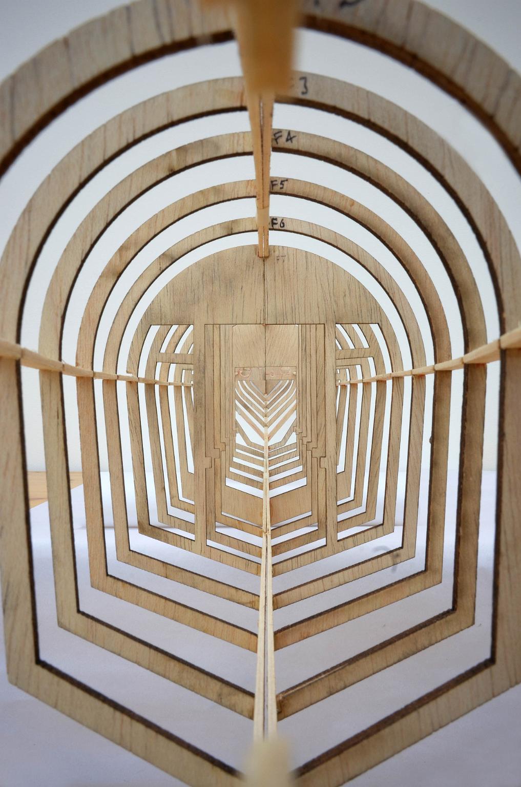 After cutting upper and lower keel pieces and pinning them on to the plan, the
two fuselage halves quickly went together, then glued together for the finished fuselage.
There is always an irresistible urge to look down through your newly constructed fuselage.
The first time I did this was sixty years ago with my KeilKraft Cadet! The fuselage was
completed with the installation of the central box girder which doubled up as wing support,
servo holder and battery box.
After cutting upper and lower keel pieces and pinning them on to the plan, the
two fuselage halves quickly went together, then glued together for the finished fuselage.
There is always an irresistible urge to look down through your newly constructed fuselage.
The first time I did this was sixty years ago with my KeilKraft Cadet! The fuselage was
completed with the installation of the central box girder which doubled up as wing support,
servo holder and battery box.
After cutting upper and lower keel pieces and pinning them on to the plan, the two fuselage halves quickly went together, then glued together for the finished fuselage. There is always an irresistible urge to look down through your newly constructed fuselage. The first time I did this was sixty years ago with my KeilKraft Cadet! The fuselage was completed with the installation of the central box girder which doubled up as wing support, servo holder and battery box.
As with the B-36, the wings were to be of foam/veneer construction. Details were sent off to Bill Manley (he advertises in the BMFA mag) and the wings were delivered a few weeks later. I decided to do the tail feathers the same way, but this turned out to be not a good idea due to inaccurate cutting and unwanted weight at the tail end.
A selection of Hobbyking motors and propellers were purchased for performance testing. Watts, rpm and thrust were measured for various combinations of battery, motor and prop. The CF2805/2840kv was the final choice of motor along with the Dalprop 4040 4-blade propeller, which happened to be almost scale size! I opted not to scale down the power output of the 3000hp 28 cylinder Pratt and Whitneys or I would have been looking at 45Kw motors!
I formed the wing floats in blue foam and skinned them with glass cloth. The motor cowlings were fashioned out of 0.25mm plasticard.

The model was covered in Silver Solartex (which is not available any more but I was able to get factory seconds). I found it difficult to apply, but after a word with Andrew Hardman (of Solarfilm), I developed a technique which involved using tissue paper between the iron and the material while turning the temperature up to 132°. Wing floats and motor nacelles spray painted with Humbrol Silver. Cockpit windows done in black solartrim.
Batteries are shoved right up into the nose and 60g lead added to balance at the 30% MAC point.
Model Statistics
Scale 1/50 Aerofoil NACA 2415
Span 2m 78“
Weight 2700g 6lbs
Wing area 43dm² 4.8ft²
Wing Loading 20oz/ft²
Thrust max 2000g 4.4lbs
Battery 2 off 2s/3300
Power loading 107 watts/lb
Mike Pirie
Photos - Mike Pirie / Derek Robertson / Brian Cullen
click on left or right of picture to move through
slides
click off picture to return to this page